top of page
The image shows a rotary switch with a red handle and a yellow base. The switch has three positions labeled "ON," "OFF," and "ON." The base of the switch has the text "select" and "3 PHASE" written on it. This type of switch is used to control electrical circuits, especially in three-phase systems, and is commonly found in industrial or commercial settings where multiple electrical phases need to be managed.
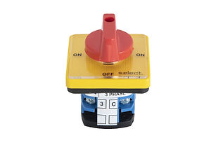
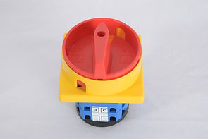
  • Standard 4 hole front panel mounting

  •  Knob/Handle operatable

  •  Suitable for 30º/45º/60º/90º/Spring Return

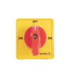
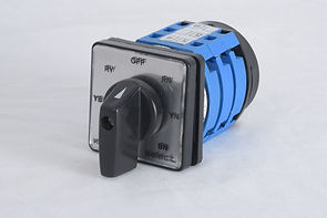
  •  Available colors : Yellow/Red, Grey/Black, Black/Black and aluminum finish.

 what is in the image The image is a table containing various types of items with corresponding measurements. The columns are labeled as TYPE, B1, B2, B3, D, F, S, W, and Max. Each row represents a different type of item with specific values for each measurement category.
The image shows a rotary switch with a yellow background and a red handle. The switch has three positions labeled "OFF" at the top and "ON" on both the left and right sides. The word "select" is written at the bottom of the switch. This type of switch is commonly used in electrical circuits to control the flow of electricity by turning the handle to the desired position.

Code-YR
Yellow Front Plate Red Knob

The image shows a rotary switch with three positions labeled "OFF," "ON," and "ON." The switch is currently in the "OFF" position. The switch is mounted on a square plate, and there is a small arrow on the switch handle indicating its position. The word "select" is printed on the bottom right corner of the plate.  This type of switch is used to control electrical circuits, allowing you to turn the power on or off as needed.

Code-GB
Grey Front Plate Black Knob

The image shows a rotary switch with a black square base. The switch has three positions labeled "OFF" at the top and "ON" on both the left and right sides. There is a white arrow on the switch handle indicating the current position, which is pointing to "OFF." The word "select" is written in the bottom right corner of the switch base.

Code-BB
Block Front Plate Black Knob

The image shows a rotary switch with a metallic finish. The switch has three positions labeled "OFF" at the top, and "ON" on both the left and right sides. The switch handle is currently pointing to the "OFF" position. The word "select" is written in the bottom right corner of the switch plate. This type of switch is commonly used in electrical circuits to control the flow of electricity by selecting different operational modes or states.

Code-AB
Alluminium Foils Front Plate Black Knob

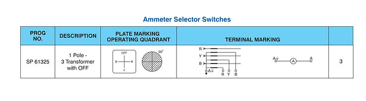
  • Measures Currents in different circuits with a Current transformer, a single Ammeter and a switch.

  • Measures voltage between phases and neutral with one voltmeter and a switch.

  • Measures voltages and currents of a circuit with one voltmeter, one ammeter and a single switch

The image shows a Phase selector  switch. This type of switch is used to control the operation of electrical circuits by rotating the handle to different positions. The switch has a black handle and a square faceplate with various labels indicating different positions: "RY," "OFF," "RN," "YN," "BN," and "YES." The body of the switch is blue and black, and it appears to be designed for panel mounting. This type of switch is commonly used in industrial and electrical applications to control machinery and equipment.
The image is a table titled "Voltmeter Selector Switches." It provides information about different types of voltmeter selector switches, including their program number, description, plate marking operating quadrant, terminal marking, and the number of terminals.

Available ampere Rating : 6, 10 , 16 and 20 Amps

The image is a table titled "Ammeter Selector Switches." It provides information about a specific ammeter selector switch with the program number SP 61325. The table has columns for the program number, description, plate marking operating quadrant, and terminal marking.

Available ampere Rating : 6, 10 , 16 and 20 Amps

The image shows a control switch panel with a lever. The panel has a square shape and contains the following text: "NEUTRAL" at the top, "TRIP" on the left side, "CLOSE" on the right side, and "BREAKER CONTROL" at the bottom. The lever is currently positioned in the "NEUTRAL" position. The panel also has the word "select" written at the bottom right corner.
  • Breaker Control Switches are specially designed for remote tripping and closing of circuit breakers and recommended wherever severe frequent operation are required.

  • To eliminate the possibility of coil burnout with two consecutive closing operation.

  • The contacts are of AgCdo , double butt type, ensuring long life and better breaking capacity.

  • High insulation in achieved by use of high quality engineering plastics.

  • The construction of our switch allows flexibility in programs with different General and Customized switching combination like stay Put (SP), Sequence locking (SL), Lost motion device (LMD), Spring return mechanism (SRM). 

GENRAL ENDURANCE

Mechanical : 1,00,000 Operations @ 300 cycle/hour

Electrical : 10,000 Operations @ 20 cycle/hour

Operating Temperature : -15 °C to 55 °C

Operating Frequency : Upto 50 - 60 kHz

TECHNICAL SPECFICATION
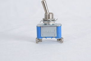
The image showcases a table labeled "Ammeter Selector Switches." This table provides detailed information on a specific ammeter selector switch with the program number SP 61325. The table includes columns for the program number, description, plate marking operating quadrant, and terminal marking. It describes the switch as a 1 Pole - 3 Transformer with OFF, detailing its configuration and wiring, which includes terminals labeled R, Y, B, and A, along with a connection diagram showing an ammeter connected between two terminals labeled A. This information is essential for understanding the switch's design and proper installation.
  • Four hole mounting

  • Easy termination

  • Available upto 32 Amps

​

The image shows a rotary switch with a red rotary knob and a handle, mounted on a yellow square base. Below the base, there's a blue and black component with white labels that likely indicate electrical connections or settings. This type of switch is commonly used for controlling electrical circuits and can be found in industrial or machinery applications.
The image is a table that lists various dimensions for different types of items. The table has columns labeled "Type," "A," "B1," "B2," "B3," "D," "F," "S," "W," and "Max." The rows in the table correspond to different types of items: "S10 / S12," "TP16 / TP20," and "S25 / S32." Each cell in the table contains numerical values that represent the dimensions for each type of item.
The image shows a toggle switch. The toggle switch has a metallic lever that can be flipped to different positions to open or close an electrical circuit. The body of the switch is blue with a metallic top and bottom. There are two screw terminals at the bottom for connecting wires. This type of switch is commonly used in various electronic and electrical applications to control the flow of current.
  • Toggle Switches type TS conforms to IEC 60947-5-1.

  • Housing : Thermoplast Moulding.

  • Termination : Screw/Soldering

  • Operating lever has a metallic seal for protection against harsh operating conditions.

  • Application : Construction and agriculture equipment, aviation facilities, office equipment, factory floor machinery, Controllers, medical equipment, Valves and Vending machines.

​

The image shows a table titled "TECHNICAL SPECIFICATION," which lists various specifications for an electrical component. It includes details on contact rating (resistive) for different amperages and voltages, ambient temperature range, types of circuitry available (such as SPST, SPDT, DPST, DPDT), mechanical and electrical life expectancy, and mounting specifications. The table provides crucial information about the component's ratings, operational life, and mounting requirements, essential for understanding its capabilities and suitability for different applications.
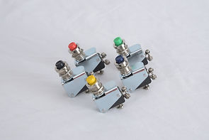
  • Snap action with precision repeatability.

  • Configuration 1NO/ 1NC/ 1CO

  • Basic Switch, with lever, with roller lever, with actuator.

  • Operating force50gms to 500gms.

  • Housing and cover : High grade engineering thermoplastic.

  • Application : Power conditioners, domestic appliances, automobile, railways, telecom, gaming consoles, automation.

The image shows five industrial limit switches clustered together. Each switch has a distinct colored button on top: red, green, yellow, blue, and black. These switches are typically used in machinery to detect the presence or absence of an object or to monitor the position of moving parts. The different colors likely indicate different functions or statuses for each switch.
The image shows a table with columns labeled "OPERATING FORCE MAX," "RELEASE FORCE MAX," and "RATING." It lists different values for each parameter. The table indicates that for an operating force max of 400 grams, the release force max is 125 grams with a rating of 10 A/250 V AC. For an operating force max of 200 grams, the release force max is 75 grams with a rating of 5 A/250 V AC. For an operating force max of 100 grams, the release force max is 40 grams with a rating of 3 A/250 V AC. Finally, for an operating force max of 50 grams, the release force max is 20 grams with a rating of 2 A/250 V AC.
The image displays a detailed specification sheet for an electrical component. It outlines various technical parameters and standards that the component adheres to. This includes current ratings of 6/10/15A for 125/250VAC and 24VDC, electrical endurance of at least 10,000 cycles, and initial insulation resistance greater than 100 megohms. The contact resistance is less than 10 milliohms, and the dielectric strength includes 1500V for 1 minute between the pole and body and 750V across open contacts. The sheet also mentions the contact gap, housing material, terminal material, contact material, fixing method, operating temperature, reference standards, degree of protection, electric shock protection class, heat and fire resistance, degree of pollution, and proof of tracking index. These specifications provide important information on the component's performance, durability, and compliance with safety standards.
The image shows a rotary switch with a black handle and a gray front panel. The front panel has a textured surface with markings, including an "I" at the top and an "II" at the bottom, indicating different switch positions. The word "select" is printed on the bottom right corner of the front panel. The switch has a series of blue and black components behind the front panel, which are likely part of the switching mechanism. This type of switch is commonly used in electrical circuits to control the flow of electricity by rotating the handle to different positions.
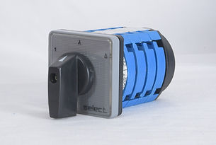
  • Motor control switches directly operate the motor with AC3 or AC4 duty rating.

  • Range : Forward Reverse , Star Delta, Two Speed Forward Reverse.

  • Colors Available: Yellow/Red, Grey/Black, Aluminum/Black, Black/Black.

FORWARD REVERSE SWITCHES

The image presents a table detailing various types of electrical switches. It includes columns labeled "PROG NO.," "DESCRIPTION," "PLATE MARKING OPERATING QUADRANT," "CONNECTION / TERMINAL MARKING," and "NO. OF STACKS." Each row describes a different switch, such as the 2 Pole switch (SP 61210), the 3 Pole switch (SP 61211), and the 3 Pole Spring Return switch (SP 61253). Information on their configurations, terminal connections, and operating quadrants is provided. This table is essential for understanding the specifications, configurations, and appropriate applications of each type of switch.

Available ampere rating : 6, 10, 16, 20, 32, 40, 63 100 and 200 Amps.

MOTOR SWITCH/STAR DELTA SWITCH

The image shows a table providing detailed information about an electrical program with the program number SP 61200. The table includes various columns: the "DESCRIPTION" indicates the switch positions as "OFF - STAR - DELTA." The "PLATE MARKING / OPERATING QUADRANT" section includes a diagram showing a switch labeled "A" with positions 1 and 2, and a circular diagram divided into 60° segments. The "CONNECTION / TERMINAL MARKING" section includes a diagram with three lines labeled L1, L2, and L3 connected to a motor symbol (M) with terminals U1, V1, W1, U2, V2, and W2. Finally, the "NO. OF STACKS" column shows that there are four stacks. This table provides essential details for understanding the configuration and wiring of this specific electrical program.

Available ampere rating : 6, 10, 16, 20, 32, 40, 63 100 and 200 Amps.

MULTISPEED SWITCHES

The image is a table that provides information about different types of motor windings. The table has the following columns: "PROG NO.," "DESCRIPTION," "PLATE MARKING/OPERATING QUADRANT," "CONNECTION/TERMINAL MARKING," and "NO. OF STACKS." Each row in the table describes a specific motor winding program, including its description, plate marking, connection details, and the number of stacks.

Available ampere rating : 6, 10, 16, 20, 32, 40, 63 100 and 200 Amps.

MOUNTINGS

The image is a table that lists different mounting codes, their descriptions, and their compatibility with various current ratings. The table is organized into three main columns: "Mounting Code," "Description," and a series of columns for different current ratings (6/10A, 16/20A, 25/32A, 40/63A, 80/100/125A, 200/400A). Each row corresponds to a specific mounting code and provides a description of the mounting type and its compatibility with the current ratings, indicated by checkmarks or specific notes.
The image shows five push button switches with different colored caps. The colors of the caps are blue, yellow, red, green, and orange. Each switch has a cylindrical body with a label that reads "select." These switches are typically used in industrial or electronic control panels to operate machinery or other devices. The variety of colors can be used to indicate different functions or statuses.
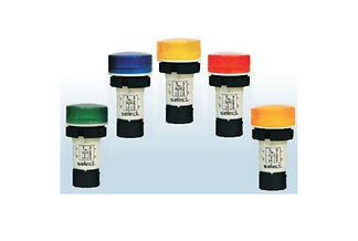
  • 22.5 mm LED indicating lamps are based on well developed solid state technology.

  • Which are robust and aesthetically designed enabling quick installation and safe operation.

  • Our LED indication lamps contains clustered LEDs which ensures diffused illumination with a Low Voltage Glow Protection(20%).

  • Application: Control Panels, Machine tools, Industrial/Commercial.

  • Colors: Red, Amber, Green, Yellow, Blue, White.  

CODING SYSTEM

This image describe the colour coding system of Indication lamp.

TECHNICAL SPECIFICATION

The image shows a table that provides technical specifications for an electrical device. The table includes details such as operating voltage options (12 VAC/DC, 24 VAC/DC, 110 VAC/DC, 240 VAC, 415 VAC, 220 VDC, and a universal range of 24 to 240V AC/DC), current consumption (maximum 20mA for AC circuits and 15mA for DC circuits), and degree of protection (rated IP 65 as per IEC 60529). It also lists applicable standards (IEC-60947-5-1), ambient temperature range (-25°C to +70°C), storage temperature range (-25°C to +40°C), life expectancy (100,000 hours), rated insulation voltage (500V), dielectric test (2.5 kV), and terminal capacity (maximum of 2x1.5mm or 1x2.5mm and minimum of 1x0.5mm). These specifications are crucial for understanding the device's performance, safety, and suitability for various applications.
bottom of page